Staff Answer
Jul 27, 2026 - 10:56 AM
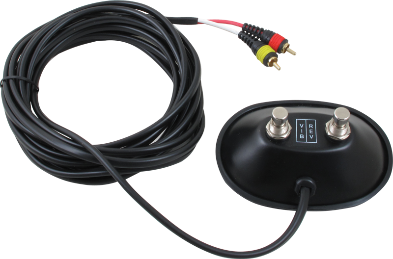
Unfortunately we do not have a schematic of this switch. If it helps, this is how continuity should measure:
BOTH OFF = No continuity between any plug contacts.
REV ON + VIB OFF = Continuity between tip and sleeve of RED plug. No other continuity.
REV OFF + VIB ON = Continuity between tip of YELLOW plug and sleeve of RED plug. No other continuity.
BOTH ON = Continuity between tip of YELLOW plug, tip of RED plug, and sleeve of RED plug. No other continuity.
As the amp doesn't send power to the swtich, you would need to add a battery, resistors, and change the switches to add the extra poles required for the LEDs.
BOTH OFF = No continuity between any plug contacts.
REV ON + VIB OFF = Continuity between tip and sleeve of RED plug. No other continuity.
REV OFF + VIB ON = Continuity between tip of YELLOW plug and sleeve of RED plug. No other continuity.
BOTH ON = Continuity between tip of YELLOW plug, tip of RED plug, and sleeve of RED plug. No other continuity.
As the amp doesn't send power to the swtich, you would need to add a battery, resistors, and change the switches to add the extra poles required for the LEDs.